Mechanical relay or solid state relay ?
This article was written because I couldn't find any solid source to answer this question on the Internet. What should you choose for home automation?
The need
You want to control appliances on the main voltage (AC source) automatically, ideally from a micro-controller. You have multiple choices here to control them.
Either you buy independent systems, that will all consume power for their own microcontroller and might fail (yet failure only break a small part of your home automation). They will also require space close to the appliance, so it's not always ideal (you can't hide all controllers in wall box for example, or your home WIFI will not reach that far).
Either you buy a large relay board with many channels and wire your home so all appliance are controlled in a central position, ideally close to the home electrical panel.
I think there is no single solution to this question and it's likely you'll choose a solution that's a mix of the above cases.
Mechanical relay
A mechanical relay is a, as name implies, a mechanical device made on a coil for the primary part of the circuit and a magnetic lever on the secondary part.
When the coil is energized (on the right in the diagram below), an electromagnetic field is generated and this attracts the lever, closing or opening the secondary circuit.
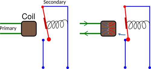
A spring might be present to open the circuit when the coil isn't energized anymore (if absent, the relay is called a latching relay).
Let's start with the good of mechanical relays:
Pros
- Cheap. Million if not billions of such device are manufactured every year.
- Safe. When opened, the secondary circuit doesn't have any current flowing. This is a safety measure that might be interesting in your home.
- Well understood by maintenance guy. If someone is going to work on your circuit, it's likely there won't be any mystery.
- Can switch large loads
And the bad:
Cons
Limited lifetime Since this is a mechanical device, the device can be operated a limited number of times. From 10'000 to 1 million times typically.
This is a very optimistic estimate. This only happens if you operate the relay in its optimal configuration (see below). In reality most relay board don't care about driving the relay in their optimal configurations, so the lifetime is close to a thousand operations before they get struck.
When this happens, the secondary circuit is always closed (energized) even if the coil isn't anymore. Depending on what's plugged on this circuit this can be catastrophic (for example, a pond pump would empty it or overfill it).
Operating power consumption Since a mechanical operation is required, a huge force is expected from the primary coil, so the power consumption is high. This is ok for controlling a short duration device like cover motors, but not for a long running device like a fan. In that case a latching relay might be more suited, but many relay board don't have the option for latching relays.
Size A mechanical device is larger than a semiconductor device. This might be an issue if you are size constrained.
Complex circuit switching Typically, when operating a electromechanical device, electromagnetic interference is generated. To avoid being disturbed by such interference, the controlling circuit must include many protections to isolate the coil from the microcontroller power domain.
Main issue with mechanical relay
This part is a bit complex to understand, so I'll write the conclusion right here and explain afterward, so you can skip it if you want:
In order to avoid wear of the relay if used to drive an inductive load like a motor/heat pump, you must use a scrubber circuit and ideally a zero crossing detection circuit, but doing so removes all advantages of the mechanical relay.
When the microcontroller decides to energize the coil current, it usually does it anywhere in the main line's period. The sequence is like this:
- The microcontroller GPIO level change will go through multiple circuits, like a transistor or an optocoupler to switch the coil's voltage
- The coil voltage induce a large change in the electromagnetic force on the lever
- Some time later, the lever starts to move.
- The lever contacts the pin on the secondary circuit establishing the circuit
- Yet, the (mechanical) energy stored in the spring has to dissipate, so the lever is pulled, breaking the circuit, causing a huge change in intensity on the secondary circuit.
- If the secondary circuit is connected to a motor (an inductance), then this high change of intensity converts to a large change in voltage on the contact
- If this voltage is higher than the voltage to ionize air (something like 1000V per millimeter), a plasma is created and a spark is generated on the lever.
- This spark increases the temperature of the lever's contact and likely remove oxydation on the contact. If the temperature is high enough, the lever's surface fuses with the secondary pin and the relay is then struck closed.
- Yet, the coil is still generating its electromagnetic force, so the lever is again attracted to close the secondary. This time, the spring's travel is lower, so less mechanical energy is stored in it
- This is called bouncing and is the main reason relays are damaged
If the microcontroller tries to break the connection on the secondary circuit:
- The spring should be strong enough to pull on the lever once the electromagnetic force is removed.
- Yet, this can happen anytime. It means it'll happen on the peak of the secondary's sinusoidal current consumption
- When the contact is broken, a huge current tries to stop flowing. In case a motor is on the secondary circuit, this converts to a large voltage
- Similar to circuit establishment, a plasma is created that could fuse the lever to the secondary circuit. The relay is struck
In order to avoid this, there are few solutions:
- Using a snubber circuit
- Switching when current is zero
Snubber circuit
A snubber circuit is a circuit that's placed either parallel to the relay's secondary contact whose role is to dampen the oscillation and absorb the surge voltage from circuit breaking.
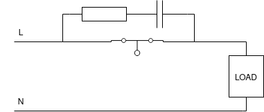
It's typically a resistor with a capacitor in series. The resistor must be small (typically 220Ω, that's 1Ω per volt) for a capacitor of 100nF (a 630V X2 capacitor is required here for the failure case when it breaks, it breaks opened). These numbers are example for a 200W motor on a 230VAC secondary circuit. Adapt the values based on your load, so that its impedance when the relay is opened is very large yet, it's able to store and release a large amount of energy upon closing. This calculator might help you.
Upon opening the circuit, a huge voltage is charging the capacitor at the same time dissipating this charging current through the resistor as heat, so it's protecting the relay's contact to a safer limit. If the voltage is below the plasma limit, no arc is created and the contact is protected.
With this circuit, however, when the relay is opened, the main voltage is still present on the secondary circuit (since it appears on the capacitor pin), so you're not isolated anymore. Not much current can leak: with the example numbers above, a 8mA current will leak for an impedance of 37kΩ, for 230VAC so it'll still be safe (under 30mA is considered safe).
The snubber circuit can also be placed after the relay in parallel to the load like this:
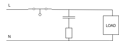
In that case, this doesn't have the leakage of a voltage when the secondary is opened, so it's preferred in terms of safety since no voltage appear on the circuit when open. However, in case of failure of the capacitor (if it's not a X2, it'll likely short), then the resistor will be powered by the main, and will likely explode (a 220Ω on a 230V source gives ~1A on the resistor and a 220W power to dissipate).
Switching at zero current
This is the obvious solution but it's very hard to do right. If it's the current that's causing the huge voltage, if we were to open the circuit when the current is zero, then no voltage spike would occur, thus the idea is to know when the relay will open and match this when the current curve is zero.
It's easier said than done however.
Finding when the voltage is zero is doable with an optocoupler and can be sampled by the microcontroller. You'll typically use an half wave rectifier before the optocoupler so you don't put too much stress on the chip's diodes.
However, if the load is inductive on the secondary (typically, a motor), the moment the voltage is zero isn't the moment when the current is zero, since an inductive load phase out the current. In addition, because the relay is a mechanical actuator, you have to account the time it takes for the relay to actually break the circuit from the moment it's instructed to do so. A typical relay is taking 5 to 10ms to actuate, so that's a quarter to half the period of the main voltage.
Worst, this time depends on the load current, so even if you measure your relay at rest, it'll likely behave differently in the real situation (not by far, but an error of 1ms is a large variation in the sinusoidal curve). This also doesn't account for the bounces (which depends on the spring in the relay, rarely described in datasheet).
So this solution is hardly solvable analytically, it's rarely implemented.
If you were to implement it, you'd need to measure the peak of the amplitude on the secondary for a varying the delay time after detecting the voltage zero on the microcontroller's GPI from the optocoupler (with an isolated ADC or oscilloscope) and try to minimize it. Save that period in your microcontroller as a calibration and never change the load or circuit.
In the end, the relay controlling circuit becomes very complex
Solid state relay
Solid state relay are semiconductor chips that let current pass through the circuit when triggered externally by your microcontroller.
Let's start with the good of solid state relays:
Pros
- Very compact. A solid state relay using come in a third to fourth the size of a mechanical relay
- Very reliable. There is no fatigue on such component unlike mechanical relays.
- Very power efficient. Maintaining the relay closed only consumes fraction of the power required for mechanical relays.
And the bad:
Cons
- More expensive. This is probably due to the proportion of manufacturing. This is changing.
- Even when "opened", the circuit isn't isolated, so you'll find the main voltage on the secondary, but no current will flow (this is painful for maintenance, since you can't figure out if the circuit is opened or closed with a multimeter for example, only a load will tell you).
- Power limited. SSR have to dissipate the current that goes through their very small resistance as heat, yet, this resistance is larger than the relay. Manufacturer usually limit the power to what the chassis can dissipate
For example, if you intend to control cover motor in your home automation, you'll need a SSR that able to switch 1A or 2A. That's very common (but take care, you need to take some margin, typically a 6A SSR is required for a 200W motor). But if you need to control an heat pump or a strong motor, then you'll have to find a 10A to 20A SSR or more, and that is less common.
Conclusion
I hope I've answered all your questions about mechanical relay and solid state relay and let you choose which one to use.