Installing RGB leds strip on your 3D printer
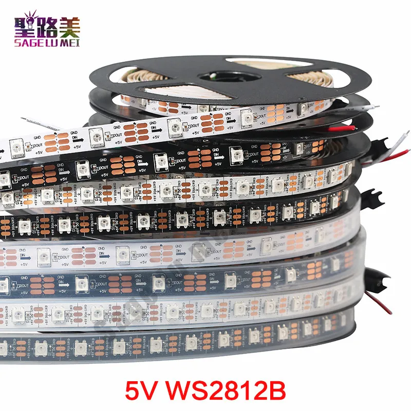
This post contains a small tutorial to describe how to install a strip of RGB(W) leds (typically WS2812B) on your printer. If you don't know what a led strip is, it looks like this:
It's a long flexible PCB with many RGBW (red/green/blue/white) LED (and a companion chip) soldered on it. It's usually very cheap (30 leds cost $2). You can install them on anything provided you have a sufficient power supply and a fast CPU.
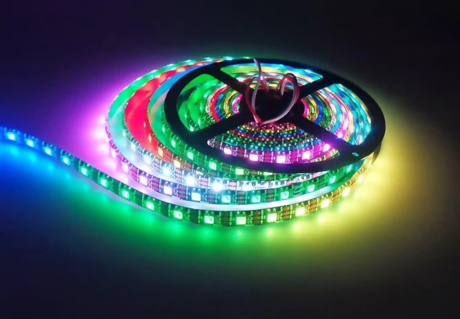
Each LED is configurable so you can have, like in the picture above, a rainbow effect, a dimmable white lighting system, an error reporting system: creativity is the limit here.
I was interested in:
- Using the LED as a status report of the printer. It's going from green to red when heating up. It's blinking upon issue (like filament runout)
- Lighting up the part being printed with dimming
- Synchronizing the picture capture (when doing timelapse) with full brightness. Even better, having a slight desynchronisation created a (false) moving light effect in the timelapse which is very nice.
Requirements
So to install such system on your 3D printer, you need:
- A LED strip (~ $2). The most common are based on WS2812B LED chip. In this tutorial, I'm using this kind, but other kind will probably work too. If your printer is black, select a black led strip.
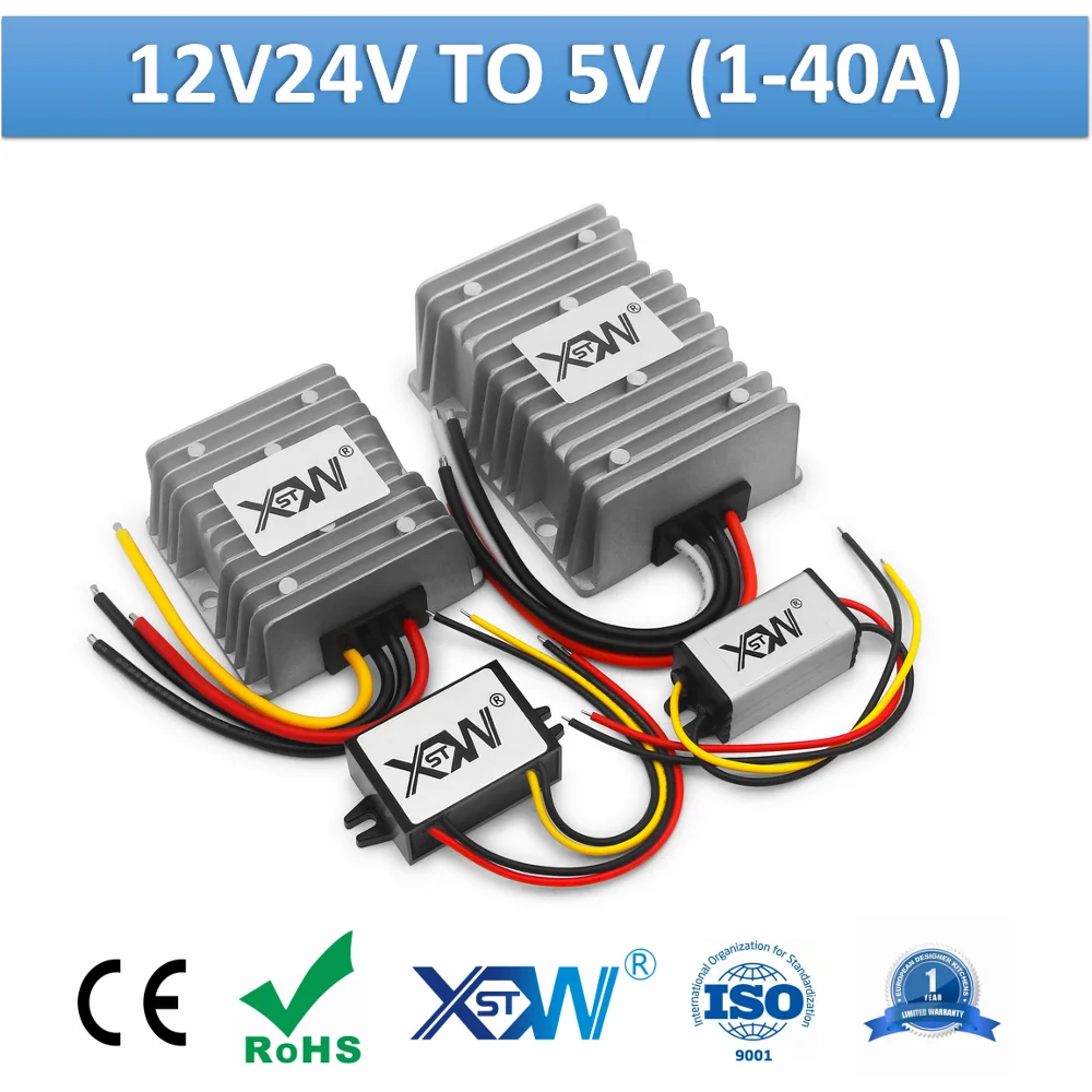
- A 5V power supply (~ $10). Usually, your 3D printer's motherboard does not allow powering the strip directly on its 5V ramp. So you need to buy a converter from the high voltage DC output and 5V (either a 12V or 24V to 5V power supply). If your printer is usually using 12V, buy a 12V to 5V else buy a 24V to 5V version. You should select a converter that's able to dissipate thermal energy (via its casing), so don't go too cheap here. See below for some calculus
- A motherboard with enough power to send the correct signals to the strip. A board with ARM chip with at least 48MHz CPU frequency should be enough for the job.
- Marlin's software. It might be possible to use another software on the motherboard, but this tutorial is using Marlin
Electronic
To avoid making mistake, you must understand few rules for selecting the power supply and the strip. When you buy a LED strip, the supplier tells you the maximum power this strip will consume at full load. For example a typical 30 LED strip with WS2812b will consume 9W, on 5V power supply. This means that a bit less than 2A will flow through the wires.
Power supply
Usually, the 5V on the printer's motherboard is made for few watts, so you can't drive 9W without triggering the motherboard protections (if any) or burning it. You don't want that, so you'll have to supply 5V by yourself, using an external power supply.
Yet, you must take some margins when selecting such power supply. Don't believe Chinese unit system here, and overallocate your Amp budget. So a Chinese's 2A power supply will not be enough. Buy at least 4A here (or, like me, 5A).
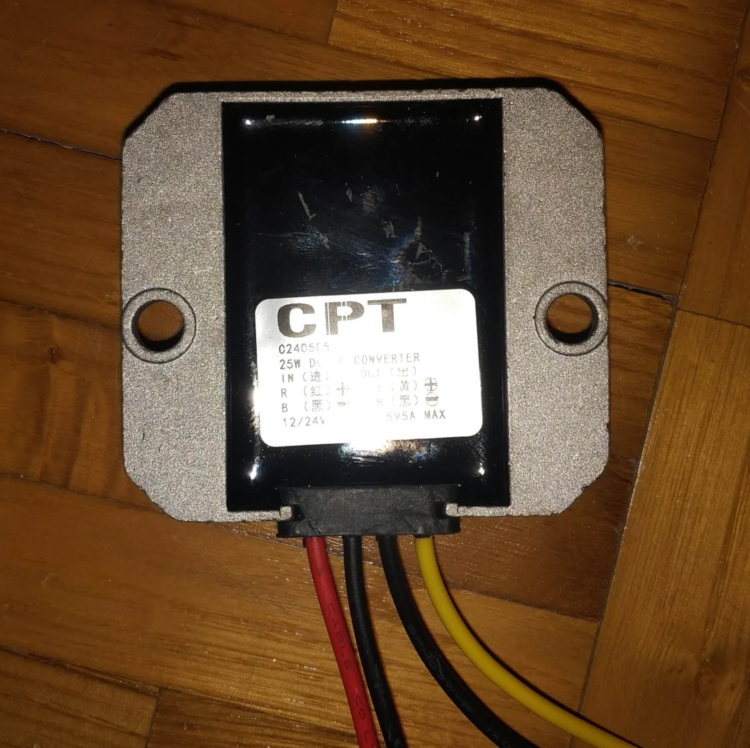
A power supply is not perfect, let's say it has a 80% efficiency. This means that when powering a 9W strip, it's consuming 11.25W, so 2.25W must be dissipated to the environment. If you buy bare DC/DC step down converter, you'll to stream air to dissipate the energy so it's an additional fan to use. Instead, you'd buy a version with a large aluminium chassis and connect it to the printer's chassis as a heat dissipator.
My power supply is like this, a 24V to 5V 25W version:
I first placed the PS in the chassis to ensure the wire length are enough to connect to the main power supply, and marked the screw position like this:
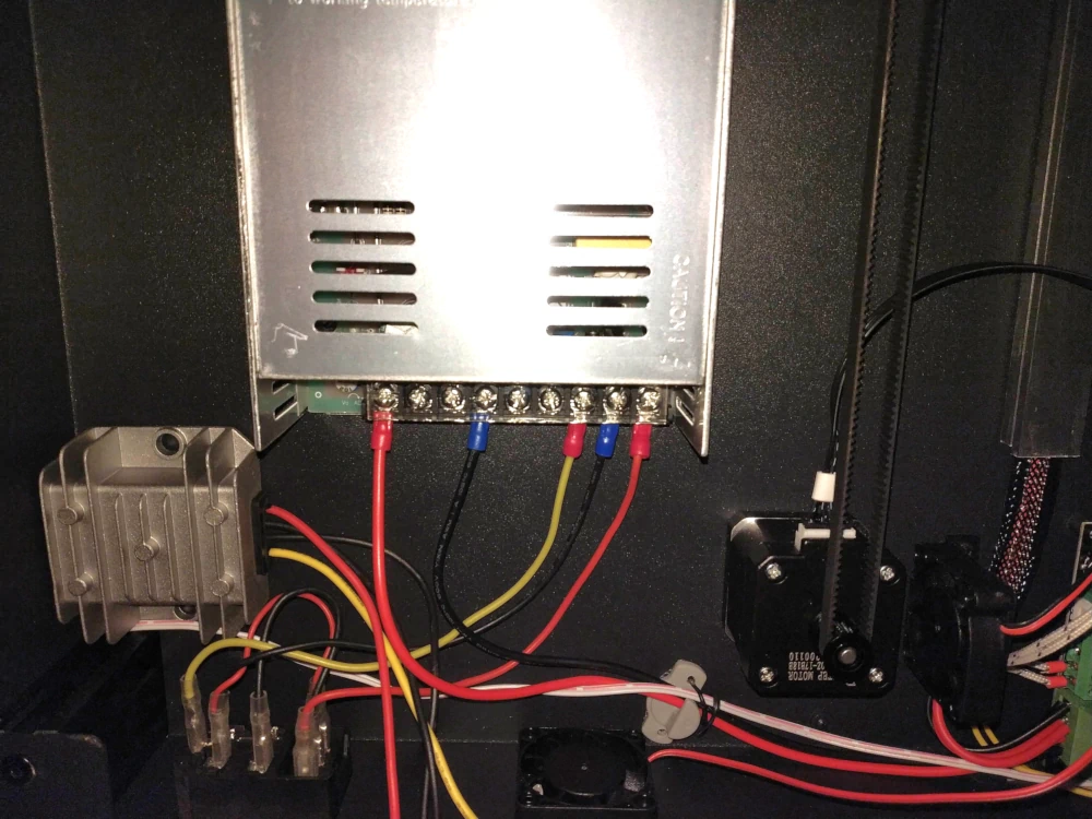
Then I scratched the paint on the chassis to expose the bare metal. I've tried to solder on the bare metal, but my flux wasn't good enough to unoxidize the metal and it did not work. Instead I glued the screws upside down with epoxy:
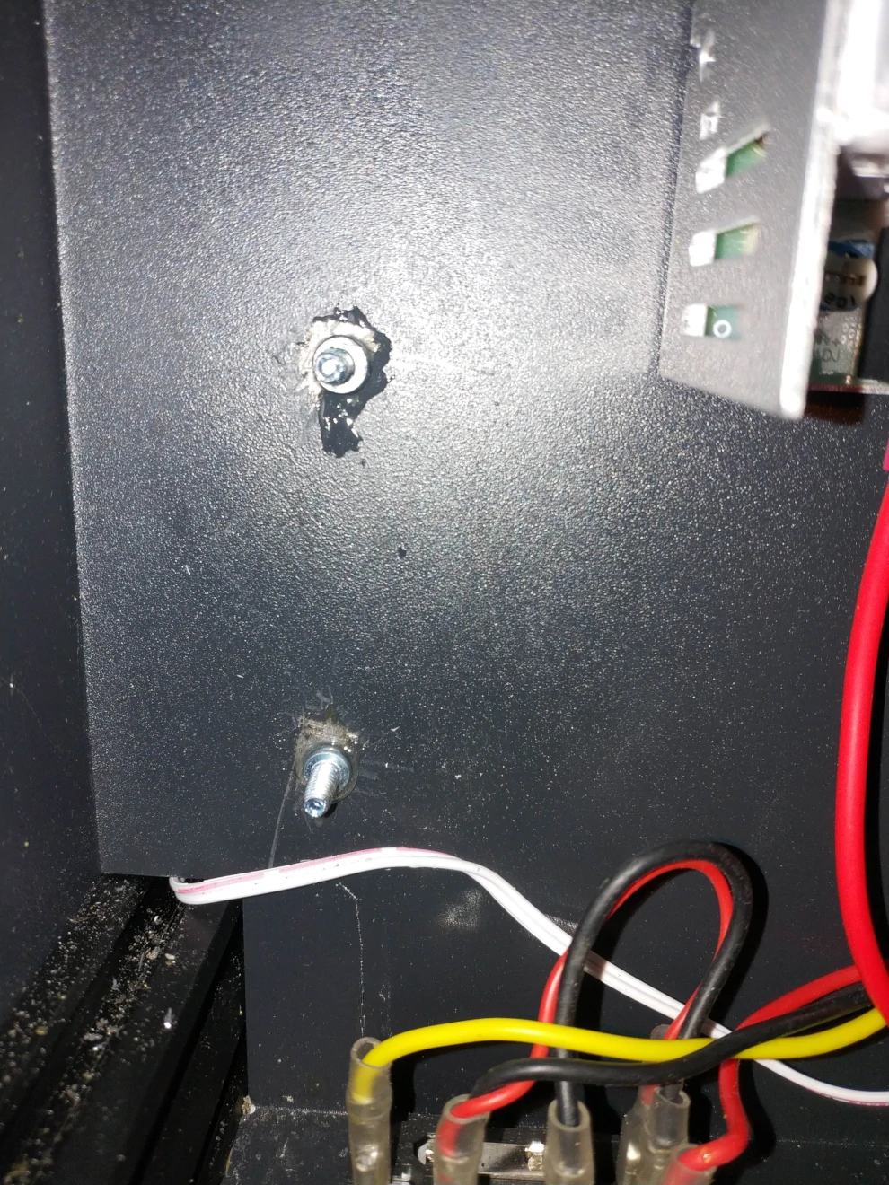
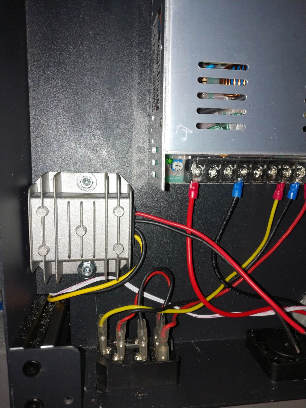
Final installation look like this:
Strip
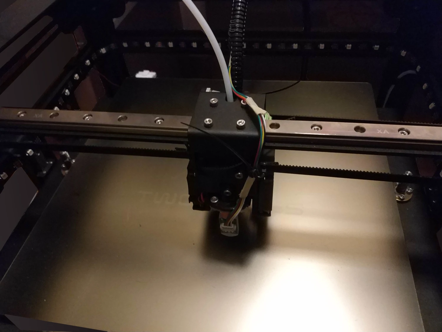
You need to prepare where you'll install the wire strip. On my printer, since it's a Core XY, I had good luck that the print head is at the same level as the lateral beams, so I only had to add the last side's beam on the back. I've cut a piece of pinewood, routed it for inserting the LED strip and painted it in black.
Wiring
Wiring is a bit more complex here. I can't tell you exactly where you'll have to plug the signal line, since it depends on your motherboard. You need to look for a GPIO that controllable at high speed (800kHz) at least. Depending on your CPU, you might search for timer's output pins (sometimes called timer's Channel) for better performance. On commonly found STM32 microcontroller, you can drive the strip on any pins, but this requires CPU burning power uselessly counting cycles and not printing. On a specific timer pin, it'll be faster since it'll use a DMA and a timer instead of the CPU.
I have a MKS Robin Nano V1.2, and in my case, I've the choice to either plug the strip data line on the PA2 (for timer based control) or PB2 for bit-banging GPIO control. The last case is the most compatible solution for now even if it's far from optimal.
You'll need to solder both GND from your motherboard and from the power supply so the power supply is not floating anymore.
The wiring will then look like this:
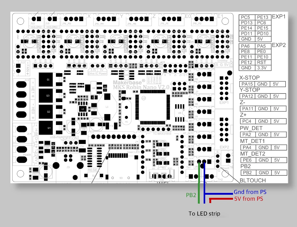
Beware however that the both the 5V and GND wire must be large wire since they'll see 2A in them. So use at least an AWG20 wire (that's 0.5mm2).
Those wires are not moving so it's safe to solder them and protect them in heat shrinking insulator.
Software
Driving the LED strip data line correctly depends on the capability of your microcontroller to generate signals with the right timing. Because there are many LED controller on the market, Adafruit has written a library abstracting away the difference. It's called NeoPixel and it's included in Marlin.
Unfortunately, until Feb 4th of 2021, it was not possible to use a STM32 for driving such library so the feature was disabled in Marlin. The main issue was with the STM32's (and many other ARM CPU) not generating correct delay for the high and low bits so the pixels were not understanding the right bit value.
I've submitted a pull request to fix the bad delay and it was accepted and merged in the bugfix-2.0.x branch.
It'll appear in the next Marlin release with hopefully, complete support for Neopixels. Meanwhile, you can fetch the bugfix branch and compile your firmware as usual and you'll have full support for Neopixels even on STM32 CPU.
Once you've enabled and configured the output pins (in Configuration.h), you'll be able to submit commands to the strips to get the color you want via the G-Code M150.
For example, sending M150 I0 P255 B0 R0 U255 will give you:
![]()
The syntax is straightforward (in the command above):
Ixxis the index of the LED to control (without theIstuff, you're driving all LEDs the same)Pxxis the brightness to use. Set to 255 for full brightness, 0 to blackRxxis the amount of red color to use (in range 0-255)Uxxis the amount of green color to use (in range 0-255)Bxxis the amount of blue color to use (in range 0-255)
New features in latest Marlin
If you have a MKS TFT35 screen, like the one from Sapphire Plus printer, then my PR should fit you.
It adds a LED strip control menu so you don't have to deal with G-Code anymore.
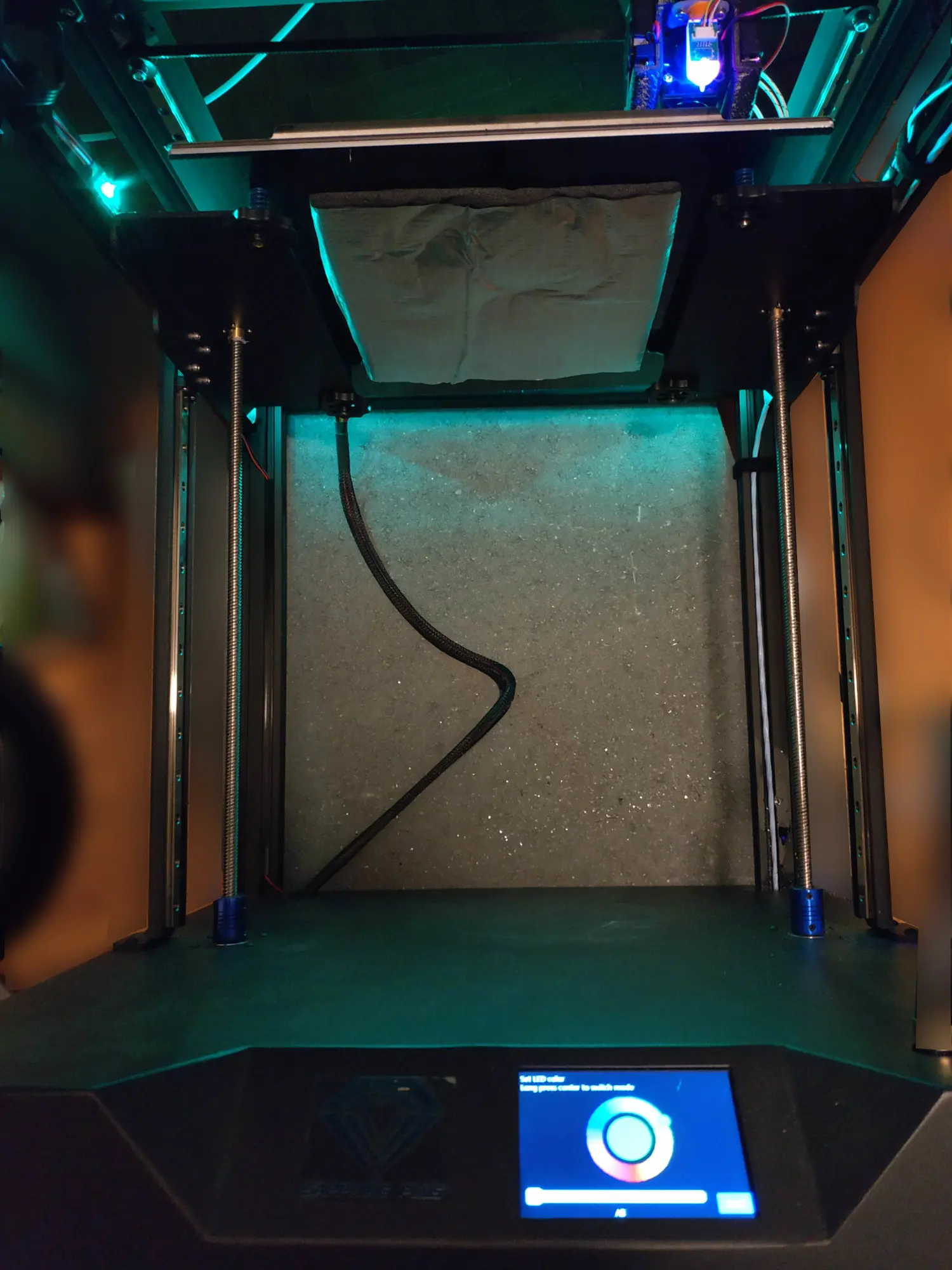
Results
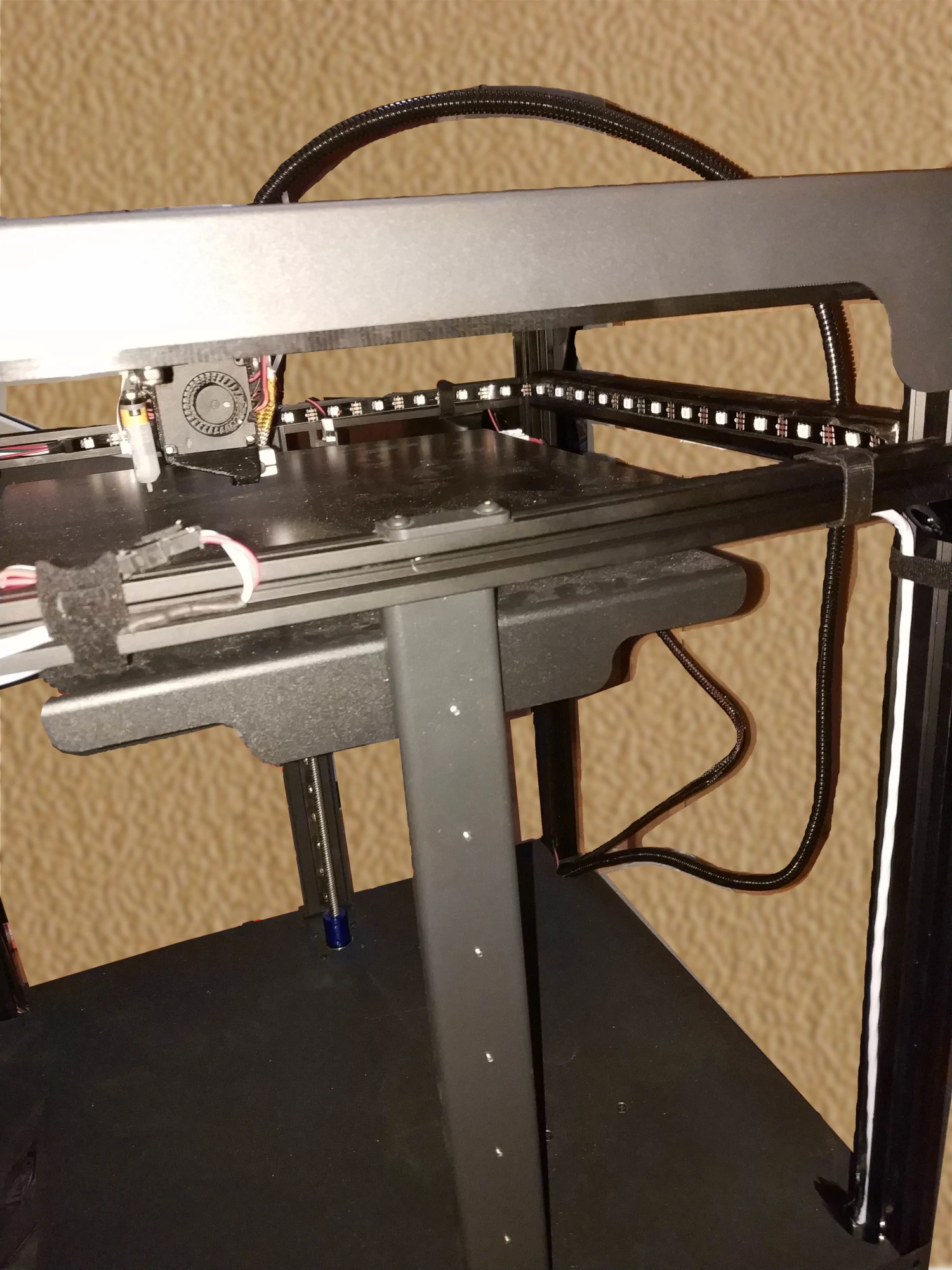
Once installed on the printer, you'll get this:
You can use the pillars to draw wires discretely:
With new Marlin version including my changes, you'll get this menu:
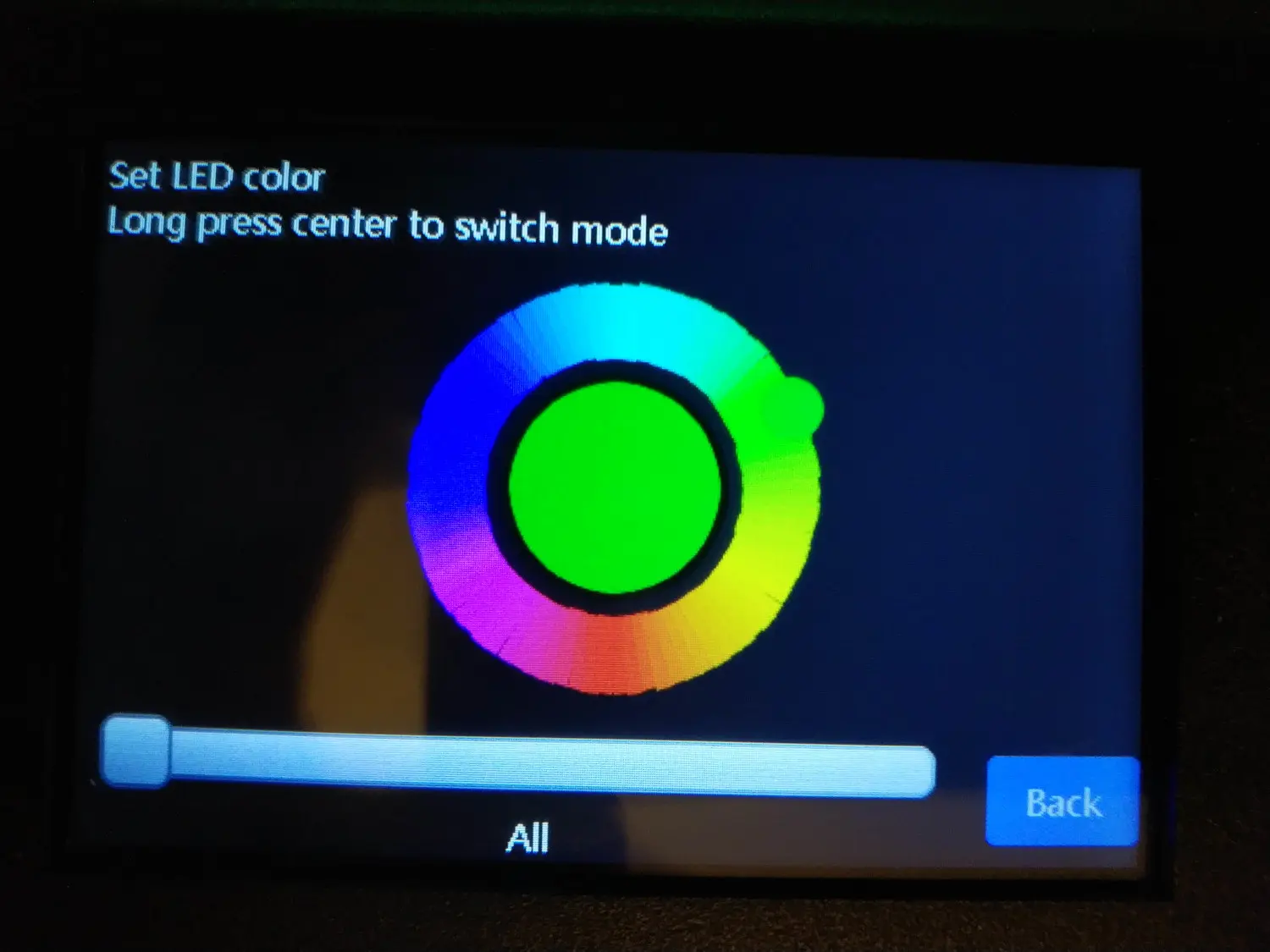
From where you'll be able to control your printer's LED strip:
Sponsored links
In order to pay for infrastructure cost for this blog, I'm listing some affiliated links about the hardware listed above.