Sapphire Plus 3D printer upgrade : Installing a BLTouch sensor
If you think that manual leveling your bed is a real pain each time you start printing (and particularly if you have a removeable magnetic print bed), then adding a BLTouch sensor will likely save you a ton of times and freedom of mind.
Here's a tutorial about how to do it for the Sapphire Plus printer.
This video is useful to understand what we'll do:
Step 1: Printing a BLTouch support
This depends on the hotend you have installed. It can be as simple as this: BLTouch mount by TwoTrees
Or, if you have updated your printer to use a E3D hotend, you'll find the piece to print in PETG here.
Step 2: Wiring the BLTouch
Sapphire Plus connection holes are kind of stupid. The mainboard is in front of you, yet they've preferred to dig a hole at the back of the printer so that wire need to go to the back then to the front in the bottom chassis. In the end, the required wire's length is too long to fit the provided wire extension in the delivered BLTouch sensor so you need to cut and add something like one meter of additional cable. Not sure it's good for the signal, so I've twisted these wires hopefully making them less prone to noise.
In my case, I'm keeping the Z-Min endstop sensor, so I'm plugging the BLTouch to the Z-Max endstop sensor, following this wiring:
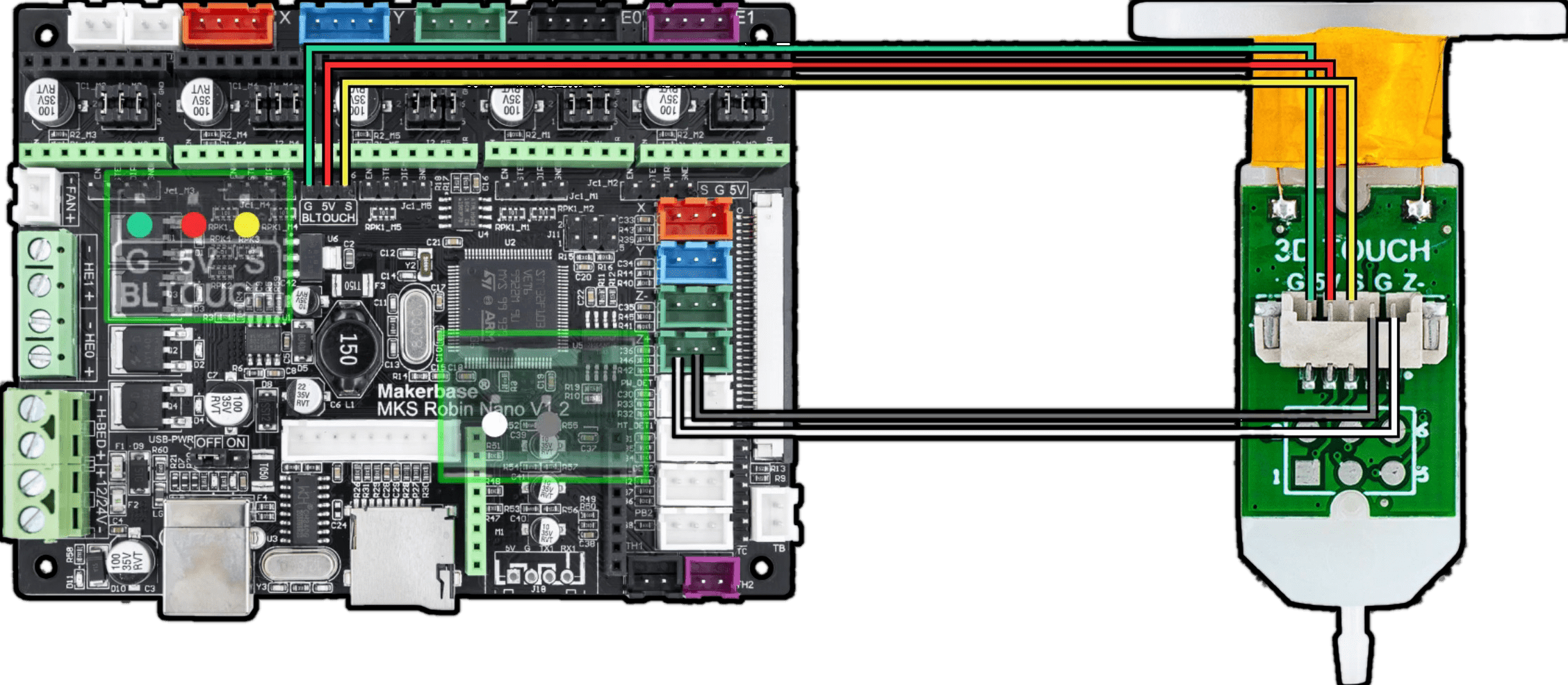
Beware of the signal order, don't trust the wire color. You'll need to trust the signal name on the PCB here
Beware about the mistake I made initially: the other endstop are simple switch, so they are plugged with the black wire on the left so you might think that the ground pin is on the left of the connector: It's not!
Mistake
So, when I plugged mine this way, I made a mistake:
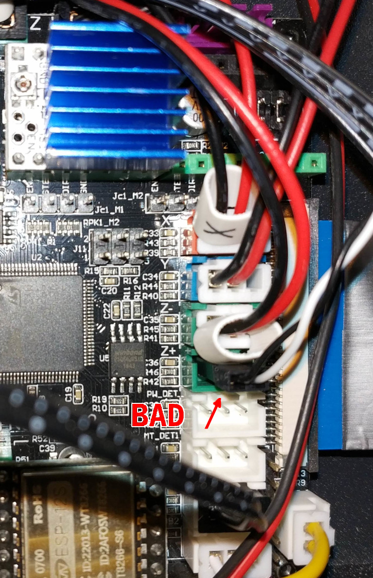
The black wire should be the center pin (so it should have read: White Black, and not Black White).
Step 3: Hardware check
Ok, now you've wired the sensor correctly, you need to test it. Without powering the printer up, and with a multimeter, ensure you've a connection between the GND of the mainboard and the two G pin on the BLTouch. Then power on the printer and ensure you have 5V on the 5V pin of the BLTouch.
If it does not show the expected tension, power off and double check the connections.
Step 4: Software part
This part is the most complex in the installation, you'll need to rebuild a Marlin's firmware for your printer by including the BLTouch in the configuration.
I'm describing how to build a new firmware here (soon).
EDIT: Due to change in hardware configuration of the printer with recent version, this doesn't make sense anymore. The new version uses 2 motor drivers for Z axis with 2 end stop detectors. Mine only use one.
The pins used for the BLTouch is different between this version. So you'll need to tweak a Marlin's configuration for Sapphire Plus based on your version (2 or 2.1). Please refer to Marlin's configuration directory here
Step 5: Calibration
The BLTouch communication protocol is strange. They use a servo command as the communication layer, so there's only few command you can send to the sensor, and they are based on the virtual "orientation" of the servo.
To send command to the sensor, you'll need to emit servo command via the G-Code console in Marlin (my PR was accepted and will be available in version 2.0.8).
The available angles are:
| Angle | Meaning | G-Code |
|---|---|---|
| 10 | Deploy probe | M280 P0 S10 |
| 90 | Pulls pin | M280 P0 S90 |
| 120 | Self test - push/pull the pin endlessly | M280 P0 S120 |
| 160 | Release touch down alarm | M280 P0 S160 |
You can then calibrate your system.
Step 5.1: Finding the X/Y offset from the nozzle to the sensor's pin
This part is quite easy, you'll need a sheet of paper.
- Take a small pen and write a small dot on the paper.
- Move the paper on your bed so that the dot is below the nozzle. Tape it to the bed. You might need to adjust the bed offset so that the nozzle does not scratch the paper.
- Issue a
M114G-Code command via the serial terminal or the G-Code console in Marlin. - The printer answers with its current position (for example:
X150.00 Y150.00 Z:00.00), write it down to remember it - Deploy the pin with
M280 P0 S10. If the pin jumps back, you'll need to release the alarm, lower the bed and deploy the probe again. - Then using the Move menu, move the hotend until it's exactly above the dot on the paper.
- Issue a
M114again and write down the values again (for example:X:150.5 Y:101.6 Z:00.9). Perform a subtraction here to find out the offset of the probe (for example:X:+0.5, Y:-49.4 Z:0.9) - Then go in the settings page and enter the X-Y values in the leveling menu, probe offset items (beware of the sign here, Y is likely negative here if you used my model)
Step 5.2: Find the Z offset
Although the previous steps gave you a Z-offset, it's not precise (what's the point to have a precise probe if we use an imprecise offset here?) So you'll need to perform a manual Z calibration, and I promise, you will only need to do this once. This is to globally level the bed.
The step by step is as usual for manual calibration:
- You can untape the piece of paper.
- Screw the four spring/screws under the bed so they are in tension and you'll be able to release them for adjusting them.
- With a key, adjust the Z-stop so that the sensor touch the bed without triggering completely (when you'll release the screw, it'll trigger the sensor)
- Home the printer to trigger the sensor. It shouldn't crash into the hotend.
- You move the nozzle to a corder of the bed (go slowly here to avoid scratching your bed) while moving the piece of paper. It should slide without being forced.
- Once the nozzle is on a corner, adjust the spring/screw under the bed so that the paper is sliding with a small friction force.
- Slowing move to another corner and do the same (repeat for all corners)
- Go to the center and ensure it's not scratching the paper
Once all those steps are done, we can calibrate the probe Z-offset:
- Home your printer
- Move the bed down a bit (5mm should be enough)
- Deploy the probe with
M280 P0 S10 - Lift up the bed slowly (by 0.1mm range) until the probe triggers. Write down the Z position (it's visible in the top left corner of the Move menu if you are using my PR, or Marlin version 2.0.8). Else you can issue a
M114command. - Go to the settings/leveling menu of the printer and set the Z-offset with the value you've read (for example, if your Z is at 0.9mm, enter 0.9 in the Z-offset)
Step 5.3: Test it's working
To test your setup is working, you can select the AutoLeveling command in the printer's menu. It should move to a corner, deploy a probe, move the another corner, deploy the probe and so on.
If it finished probing the complete bed, you're done, congratulations!
If it stops midway, you'll need to run the command G29 in a serial terminal to watch the error message and, hopefully find out what went wrong.
Troubleshooting
The printer probes outside of the bed, or crash on a side
You've probably inverted the Y-offset (or X-offset). Negate the offset in the menu and retry
The probe deploy on the first corner but stops here
The Z-offset is not correct, so it waits to be triggered, but the printer already reached the Z-0 position. Either move the Z stop sensor up a bit so the bed can trigger the probe while going up (make sure the bed is not crashing into the nozzle here) or move the BLTouch mount down (unscrew the mount, slide the BLTouch sensor down a bit and retry). You'll need to re-calibrate the Z-offset again
The probe is blinking in red
The probe has triggered an alarm. If it happens while it's not touching the bed, something is wrong in the wiring here.
Sponsored links
In order to pay for infrastructure cost for this blog, I'm listing some affiliated links about the hardware listed above.

