So you've decided to buy a Sapphire Plus printer (maybe after reading my review). You've received it and now, you start the puzzle...
Building a Sapphire Plus printer: a good tutorial
Well, the manual includes few pictures and its wording is poor. I'll try my best to list the operations required to build the system.
The manual is available here.
Step 1: Install the base chassis
Since everything will be dependent on the base chassis, you must make sure the wiring is correct first, before installing the side columns, it'll be much easier to fix if you don't have the top part when tilting the machine.
On my system, there was 3 cable trays with only one containing some wires in it. Unfortunately, the wired wire was wrong.
In your system, you'll have this once it's plugged (don't plug it now, but be aware about how it will look like once it is, so you'll be able to stop any error before making them):
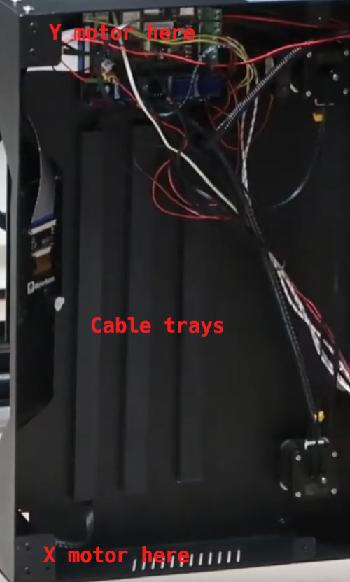
You must follow the cable that's inside the cable tray to make sure it's labelled X motor and that it goes to the X motor position (as shown in the picture above). Similarly for Y motor.
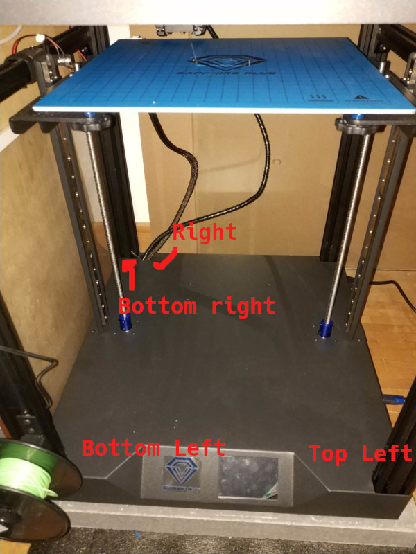
For now on, I'll call the bottom left hole the cables that must go through the X motor label, and top left those that should go to the Y motor label, bottom right for the other cables (most of them), not shown in the picture above and right for the hole on the right used by the bed and hotend, it's the only true round hole on the base.
In the bottom left hole, you'll have:
- The X Motor cable
- The Filament sensor cable
- Z limit switch (my machine only had one, it seems some machine have both)
In the top left hole you'll have:
- The Y motor cable
In the bottom right hole, you'll have:
- Y limit switch
- X limit switch
- Neopixels (if any)
In the right hole, you'll have:
- Hot bet large connector
- Hotend heating resistance (the wire with fiberglass coating)
- Hotend thermal sensor wire (very thin wires)
- Hotend fan wires
Seen from above, it'll look like this:
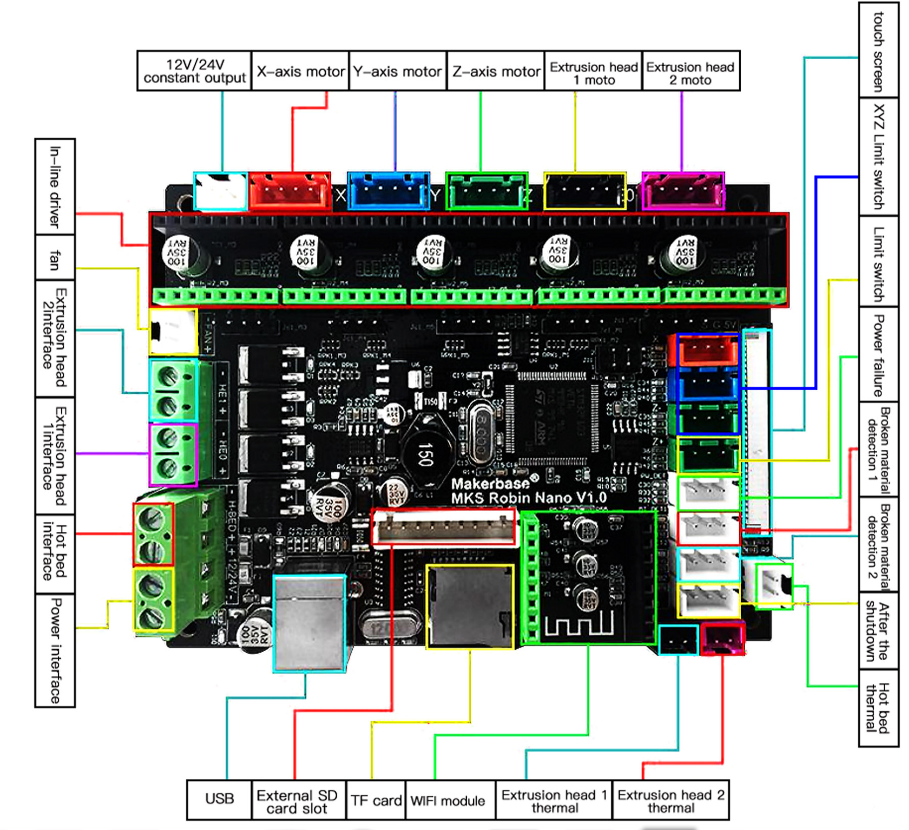
The wires will be connected to the MKS Robin Nano V1.2 board following this pinout: