Parametric connector for 2.54mm pins
This model is a parametric connector (male, female and locking thumb) for 2.54mm pitched pins.
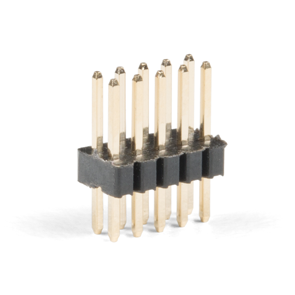
2.54mm is the most common pitch for pins, like these:
Why would you want a parametric connector or being able to print such connector?
If you use a board with very large connections (like 2 x 11pins in a row), and those going to different sensors, you'll end up with either independent female connector and a mess of cable when you need to plug these on the male pins. Also, usual female connectors don't have any locking system preventing disconnection when pulling on the cable.
So the model below allow to generate any form of both male and female connector (understand: not rectangular shaped, you can finally make Tetris like connectors!), with an additional locking system preventing accidental unplugging.
It's able to generate this kind of connector:
Female
 Download
 Measure
 Section cut
Male
- Download
- Measure
- Section cut
Locking lip
- Download
- Measure
- Section cut
These models are made to be printed without support, at the maximum quality your printer can reach (0.12mm or less) You'll need at least Cura 5.0 for the wall to print. The lip should be printed vertically with the grip foot on the bed. Similarly, the male part should print the grip foot on the bed too.
The idea is to solder the 2.54 pins on your PCB, then slide the (usually black) plastic part up and remove it. Then slide the male housing on the pins, with the grip foot on top. You'll need to remove the female pins from the (standard) female connector and insert in your printed version (or use a crimping tool like those below to make your own).
When plugging the female housing on your connector, you can then slide the locking lip sideway to lock the connection and prevent unplugging.
Parametric file
Ok, but how do I change the connector shape and pin layout ?
You'll need to download FreeCAD 0.20 (should be released very soon, if not grab a weekly build). In FreeCAD, you'll need to install the Lattice2 addon.
On the menu bar, click on "Tools" then "Addon Manager" and install the lattice2 workspace, then restart FreeCAD.
Then open the following file: ParametricConnector.zip
Open the file in FreeCAD, and open the spreadsheet in the left toolbar:
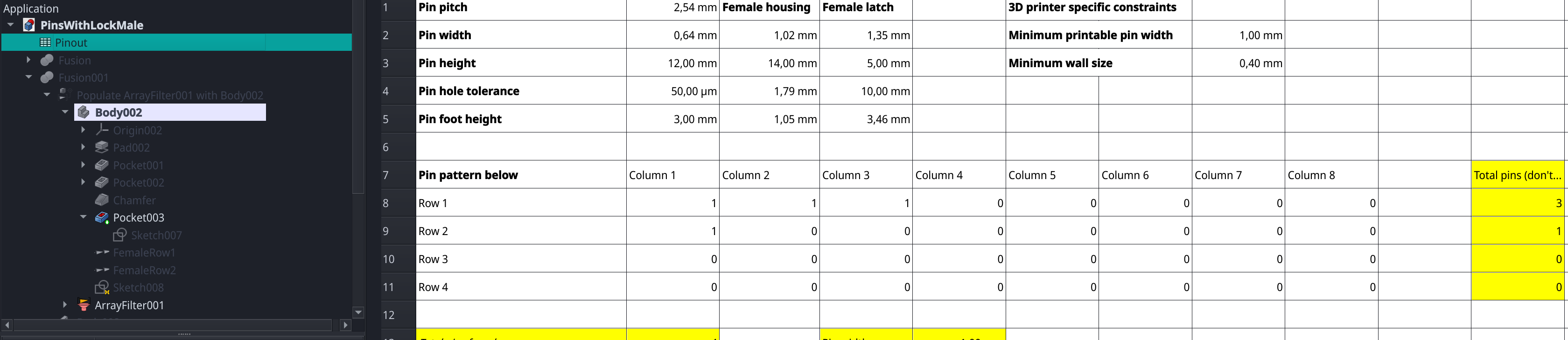
You'll usually avoid touching the top value (pin pitch, width and so on).
You can change the pin layout matrix (in B8:I11) by storing 1 where you want a pin to be and 0 where you don't want a pin. Make sure it's consistent (you can't make holes in the connector obviously).
Depending on your printer, you might need to adjust the minimum printable pin width (for a 0.4mm nozzle, 1mm is enough to ensure a good grip on the metal pin), and wall size (usually, the width of your noozle).
Don't touch anything in yellow.
Then save and FreeCAD should recompute the 3 objects in the tree to match your changes (right click on Male and select "Recompute", then on "Female", and finally on "Lip" if it doesn't)
Sponsored links
In order to pay for infrastructure cost for this blog, I'm listing some affiliated links about the hardware listed above.

