This post is a tutorial written to install the speed regulator option (usually called Cruise Control) on a Fiat Ducato X250
Enabling speed regulator on old RV
Why doing this ?
On now-old RV, automatic speed regulation was an option and wasn't probably offered to the final customer. Yet, the feature is present in the embedded computing unit (ECU) so it's possible to use it, provided the correct wiring, tools and changes are made.
With automatic speed regulation, your motor's fuel consumption will likely decrease (more so when you try to maintain a speed manually).
Also, it's providing a very convenient driving mode where you can relieve your right foot.
Finally, when selling your RV, this option increases the value of your vehicle.
What model can we upgrade ?
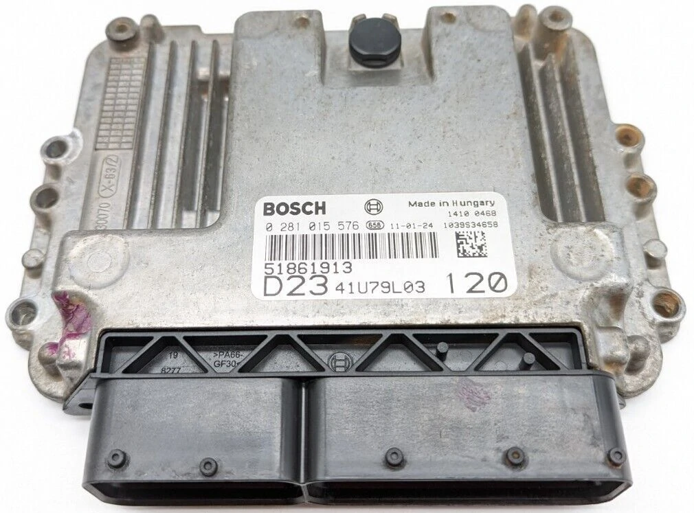
Right now, the tutorial below is for the vehicle with a ECU of brand Bosch and model EDC16C39 (the Bosch reference is 0 281 012 490). This is the model used in Fiat Ducato X250 (from 2006 to 2010, engine X250), but also on Peugeot Boxer, Citroën Jumper and other compatible brand.
Other models might have the same ECU, so they will likely supports the modifications.
How can I identify the ECU on my RV ?
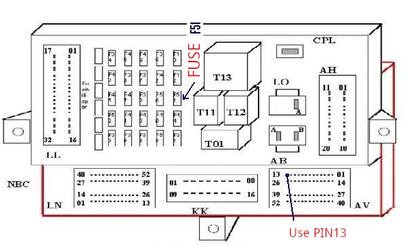
Locate the ECU following this diagram:
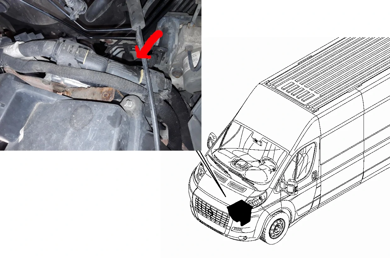
The ECU looks like this:
Does it void the warranty ?
Warranty ? What warranty ?
All those models are now outdated and out of warranty. The modification doesn't require modifying the ECU, only plugging wires in (empty) pins. So at worst, it will perform exactly as before the modification. You can remove your modifications if it doesn't work.
How much does it cost ?
You'll need:
- 4 insulated wires (with PVC insulation), themselves insulated to go from the ECU to the steering wheel. Don't get too cheap on those, a 0.5mm² (AWG20) with 10 meters will leave you plenty of margin ($25).
- Pins to clamp (you can retrieve them in old ECU from your car junkyard) or order those with the reference: 6451 Z1 from your best Chinese reseller (less than $10)
- Speed control lever (this part is where you'll make a choice, see below). From $60 (for a single lever, you'll need to cut into your steering column switch to make space) to $300 (MEAT & DORIA 23465 for complete steering column switch) depending on the cleanliness of your integration
- Half a day of work. Price is on your side here.
Let's get started!
The installation is split in multiple steps. Let's prepare everything in the comfort of your home so the time outside is minimal.
Cruise control harness
You'll need to fit the pins on the wire on one side. You should clamp them with a crimping tool but if you don't have one, you can be very careful with pliers. The wire to connect on the ECU are:
- 77 => Will be plugged on the ON switch
- 56 => Set +
- 78 => Set -
- 38 => Resume
It's always a good idea to label your wires, it'll be a lot easier when under the cover.
Lever
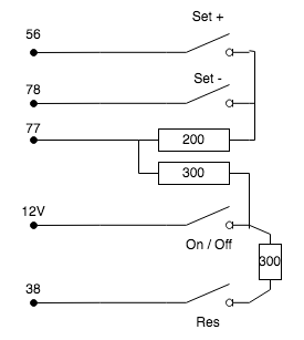
If you decide to only buy a lever for cruise control, you'll need to add resistors which might not be included in the lever.
In that case the electric schematic is like this:
The level connector is a female socket that requires a male plug with 5 pins like this:
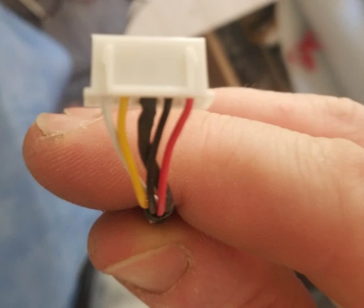 I've found mine in my graveyard of computer parts.
You might need to identify the pinout for your lever. This is done like this:
- Using a multimeter, you can identify each pin on the lever with the schematic above.
- You'll measure 500 Ohms between the 12V pin and the
Set(56 +, 78 -) pins, - 300 Ohms between the 12V pin and the
On(77) pin - 300 Ohms between the 12V pin and the
Resume(38) pin. - Press each button with the multimeter attached to find the pins.
Onmust be enabled for measuring other
12V
As you can see from the previous schematic, there is no ground on the connector, and there is a 12V (but this doesn't come from the ECU). This means you'll have to add a cable from the fuse box (on the bottom left of the steering wheel). You'll connect the cable on pin 13 of the bottom right connector, like this:
Preparing the ECU connection
You'll connect the wire with the number (they are embossed on the back of the connector, but you can follow this schematic for locating them):
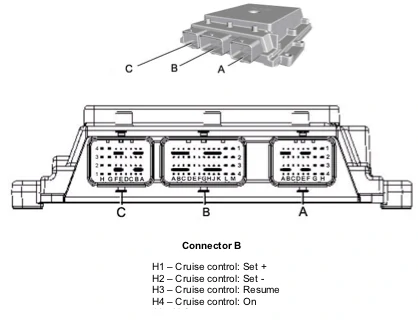
This schematic is extracted from official documentation, but they shows 4 rows while the actual connector only have 2 rows. The position is correct through, just follow the pin numbers on the connector. The ECU is upside down in your vehicle, so the B and C connector are on the right and merged together. The A connector is on the left and is a lot smaller than the other plug.
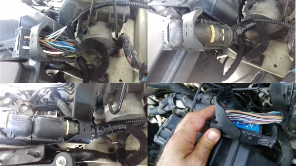
The operations to open the connector is to lift up the lever (see bottom left then top right of the following picture).
Then pull the drawer to the right to let the connector disconnect from the ECU.
You'll then need to slide the blue part along the cable to let new pins in (bottom right):
 You might need to remove yellow pins that are taking the place of the new pins like this:
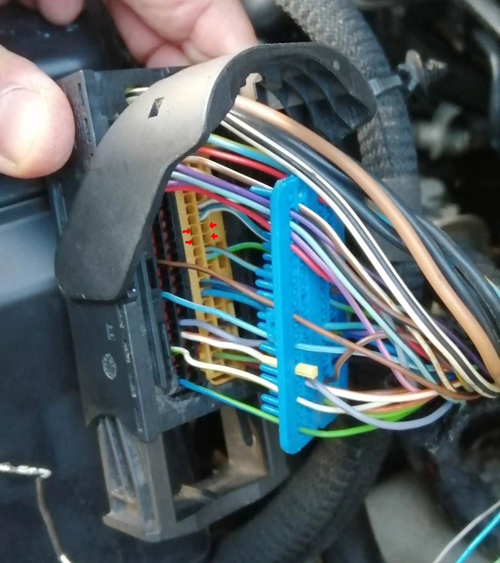
In the previous picture, I've marked with red arrows the direction of the small lever of the metallic pin you need to insert. This lever is made to prevent the pin from being retracted while pulled. You must orientate the lever so that it touches the side of the square hole marked by the red arrow.
You'll need to push with some force for them to reach the end of the socket, the metallic part of the pin shouldn't be visible. Don't be too strong, use pliers in case of doubt.
If, after all wiring work, the cruise control light doesn't show up, the most common reported issue is due to bad connection in this connector.
Replacing the steering column switch
One of my lever on the column switch was failing on my vehicle (the high beam switch, which didn't disengage correctly). So I know I had to remplace it. I've decide to change the complete column, since it simplifies the work by a lot. I've bought the steering column switch with cruise control and computer switch button (on the top of the right lever).
To replace the steering column switch, you must unplug the car's battery first and go drink a beer for 30mn at least. This will allow the airbag sensor to discharge and should avoid triggering it when unplugged.
Then you need to unclip the airbag from the steering wheel, and this is like gynecology. It's almost impossible to do without a diagram because you don't know where those clips are. Your only access is from the back where you don't have enough space to manipulate your tools.
You first need to remove all screws around the steering wheel with a Torx screwdriver (like in these pictures):
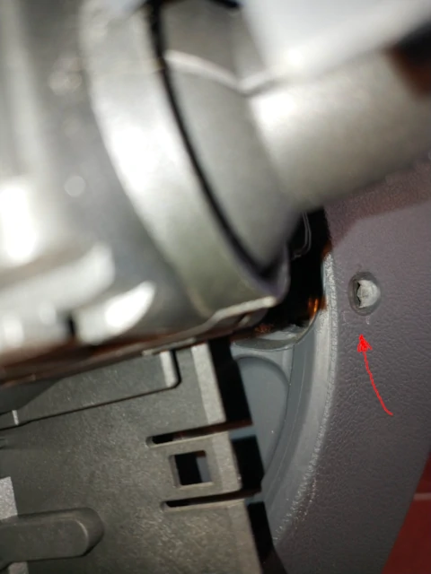
You'll then remove these plastic part that enclose the wheel and keyhole. This grants you access to few holes behind the steering wheel.
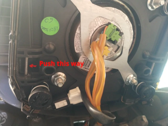
You'll need a strong and flat screwdriver that's thin enough to fit in the holes and strong enough to push on the metallic axis to displace them laterally. You'll need to push perpendicular to the axis so the clip can be released. It's not the clip (which is in metal) that moves or bend, but the axis that's translating, like in the following picture of the back of the airbag:
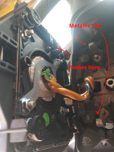
On the opposite size, you'll see these metallic clips:
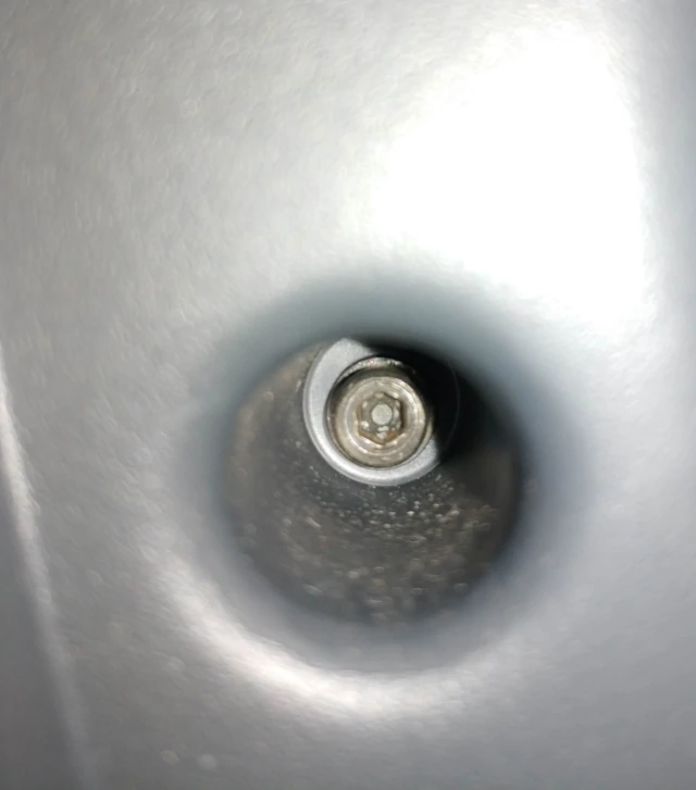
You'll insert your screwdriver in the holes around the steering wheel, like this one:
The hole gives access to the axis to push (more or less). Play a little bit with your screwdriver until you're able to unclip one side, then put some spacer to prevent clipping it while rotating the steering wheel.
Then you'll unplug all connectors carefully.
Mark the steering wheel's position with a marker before unscrewing so you'll be able to align it again when done replacing the column switch.
You'll probably sweat a lot to get the airbag off, so before pushing it back in place, I advice you ensure everything is working (see below). If it is, you'll be reassemble everything by following the same steps in reverse. Airbag just requires pushing it to clip it in place (hopefully).
Testing the functions
Once everything is connected, the ECU should light up a green symbol on the dashboard like this when the On button is switched:
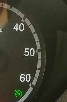
This will not happen until the ECU has tested everything. This means that you must:
- Reconnect the airbag (to avoid having a fault reported) but don't clip it yet if you need to work again on the lines
- Reconnect the battery
- Press all buttons on the lever (
Set +,Set -,Resume,On) so it can register there is a signal on those lines. Start by rotating theOnswitch, since without it, no other button will register (see schematic)
You can then start the engine to make a test on the road.
The cruise control is activated only when above a minimum speed (likely around 50km/h, I think) by hitting the Set +. In that case, the engine will maintain its speed even if you don't accelerate. You'll push on the brake or the clutch to disengage it.
Each press on Set + (resp. Set -) increases (resp. decrease) the speed by 2km/h. I don't know what Resume is for...
Troubleshooting
As usual, I describe what I did. I don't endorse any responsibility for a wrong manipulation on your side or damages on your vehicle.
Yet, if you don't have the green light on your dashboard, you'll probably need to check the connections are working on the ECU's connector.
If you've bought a complete steering column switch, you'll need to ensure you've connected the right pin to the right switch. If you have bought only a lever, you must also ensure that you have the right resistances on each pins, else, you'll need to solder some as specified.
I can't give you the pinout of the lever, they are all different (some are 6 pins, some are 5 pins), but you can easily figure this out by pressing the buttons and checking the resistances.
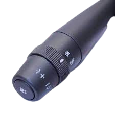
If you've found a lever in a junkyard, make sure it has at least 5 pins. If it only have 3 pins, bad luck, it's useless, since those are for CAN bus.
If it looks like this, it will probably fit:
If you need to unplug the airbag, remember to disconnect the battery first, wait 30mn before disconnecting it, else the airbag could explode.
Sponsored links
In order to pay for infrastructure cost for this blog, I'm listing some affiliated links about the hardware listed above.


