Detach and swap your hotend on your 3D printer
Sapphire Plus swappable hotend
If you have read my previous posts about replacing the hotend, you've probably already realized that changing the hotend is a tedious work.
Most of the difficulties comes from:
- Wiring the new hotend and sensors
- Mechanical and dimension fits
If you've done the work once, you probably never want to do it again. Cutting and lengthening wires is not a trivial task, and inserting wires in the flexible cable tray is a nightmare. In this post, I'll explain how to avoid this (in fact, do it once and forget about it).
The basic idea here is to bring all the hotend connections on the hotend itself, so you never have to deal with the mess again. Ideally, changing / swapping the hot end should resume to unconnecting the hotend, unscrewing it, swapping it with another hotend and connecting it back.
Something like this:
Let's follow this step by step guide to figure out how to do that:
Requirements
If you already have a working hotend, then you have almost all you need concerning wires. You'll need this:
- A PCB that can be physically mounted on the hotend support (I'm providing a version for Sapphire Plus below) where the connectors will be installed. Around $10
- A crimping tool (if you don't have one) Around $30
- A 16G0.5 shielded cable. Wires of 0.5mm2 are required for the heating resistance current. If you don't intend to use a direct extruder in the future, you can use higher gauge (lower cross section) wires but you'll need to combine multiple wire to support the current correctly. See below for computation of the wire gauge. Around $12 for 1.5m if you use my wire dispatch, 2m if you keep's Twotree's version
- A VGA subD15 connector (as pictured above). Around $0.5
- A working printer to print the connector's housing
- Patience. But you need this once only. Priceless
Step 1. Engineering work
Wire section and numbers
On my printer, the main tension is 24V. The heating element is consuming, at maximum, 40W, so it means that the current that will flow in the wire will be 1.7A (current = power / voltage).
The wire section should support such current continuously. If you refer to this table, then it means that the maximum gauge you can use is AWG20 or 0.5mm2 wire (look into the rightmost column for a current that's above what you need).
In the worst case, you can combine 2 wires for a single connection, so 2 AWG24 or 0.2mm2 wire per connection could be enough.
You'll need:
| Function | Required wires | Connected to common Ground |
|---|---|---|
| Heater | 2 with ~ 2A | No |
| Thermistor | 2 with no current | Yes |
| Hotend Fan | 2 with 0.3A | Yes |
| Lateral Fans | 2 with 0.3A | Yes |
| BLTouch | 5 with no current | 2 of them |
| X limit switch | 2 with no current | Yes |
| Extruder motor | 4 with 1.2A | No |
Check the ground connections with a multimeter in a continuity test mode.
If you count the number of required wires, it sums up to 19 wires. Yet, because most of the wires are connected to a common ground, we can bypass them in the cable, so a minimum of 13 wires are required plus the ground wire.
The most common, and compact connector you can use that provides at least 14 connections is the standard DB-15 connector. It's large so it might not be convenient. You can also use a D-Sub15 version (also known as VGA connector) that's both compact and easy to source. It's able to transmit up to 3A per pin.
I've chosen this connector here, and a flexible 16 wires cables of 0.5mm2 (AWG20) gauge. If I never intended to install an direct extrusion motor, I could have limited myself to a 16G0.2 (AWG24) or a 12G0.5 (AWG20).
PCB design
Once the number of connection is chosen, the connector type must be selected. I've chosen JST XH connectors here for all connector except for the heater element since JST XH are limited to 2A and I wanted some margin here. So for the heater wire, I'm using a screwable terminal block that supports 6A.
Since I wanted something clean, I've designed a PCB to support the wires, with the mounting hole perfectly aligning the hotend support's hole.
Here's the resulting PCB (feel free to ask in the comment if you need some for Sapphire Plus, I've few left) :
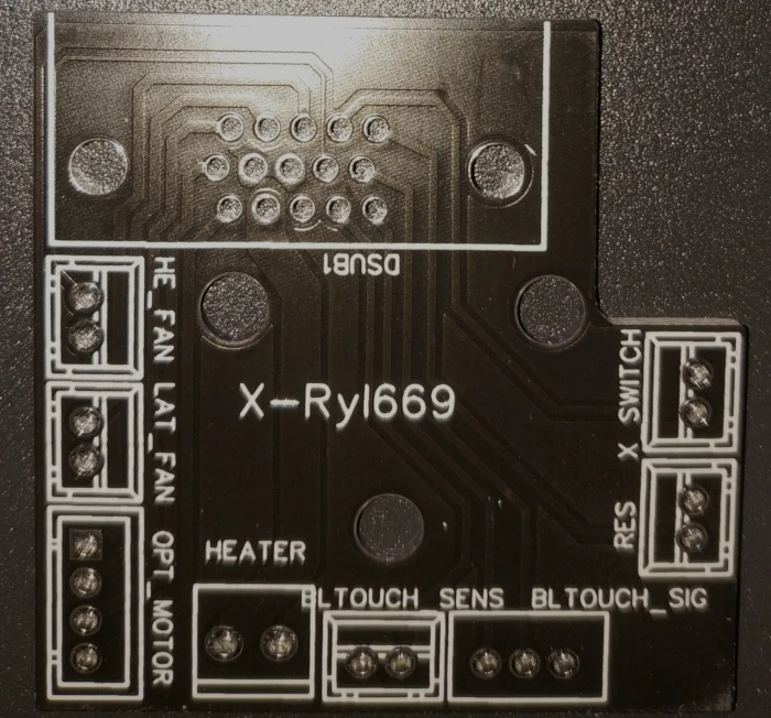
After the PCB arrived, soldering the connectors is done very quickly (provided you have a third hand), within half an hour. Just make sure of the connector orientation (if you do it wrong, you'll have to adjust the crimped wires in their housing)
Here's the pinout for the PCB above
Step 2. Building up
Crimping wires
It's absolutely required you crimp your wires. Don't solder them, even if you use a heat shrinkable tube, since these will be subject to mechanical stress and they must stay flexible.
Crimping consist in fixing this:
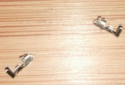
On your wires:
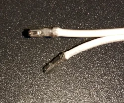
The heater wires should be crimped like this:
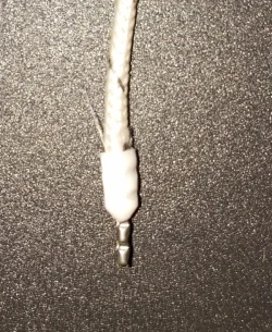
Soldering the VGA connector
You'll need to label your wire or you'll end up crazy. Fortunately, the cable I've ordered had its wire labelled so no additional labelling work was required. I've soldered the cable into the VGA connector like this:
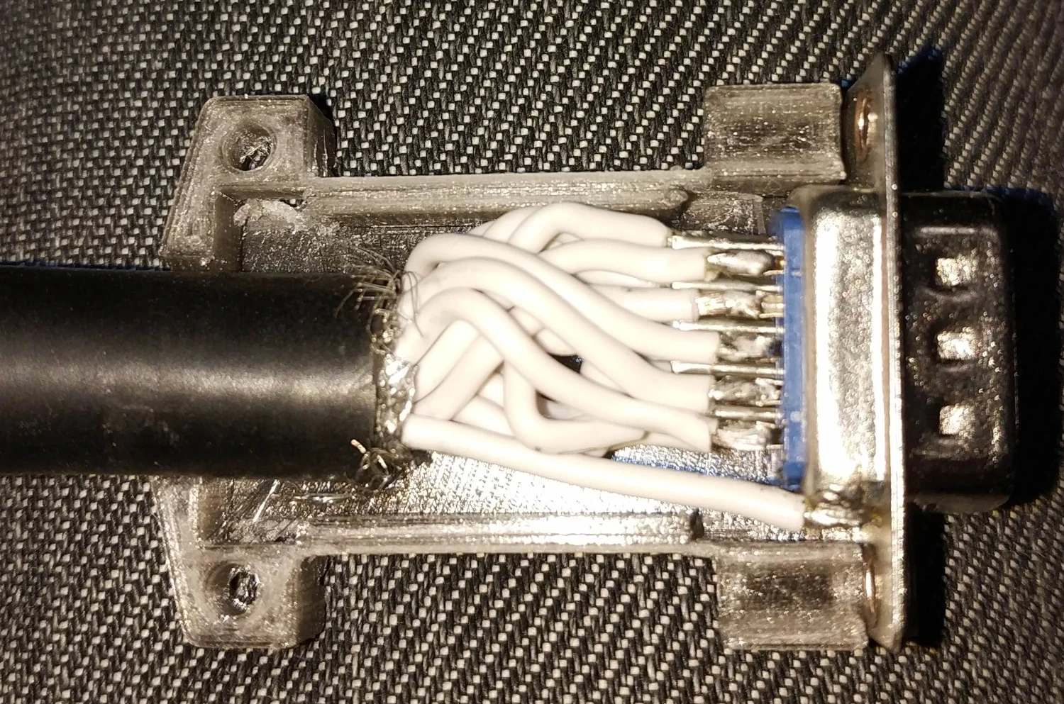
The housing of the connector was printed (I've ordered plastic housing, but they were too small to hold such a large cable), so I had to design my own:
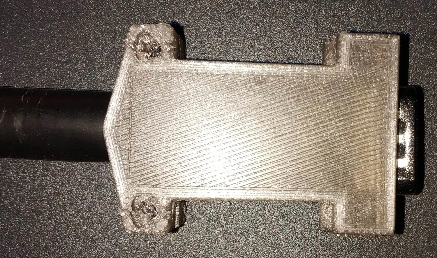
The model is here.
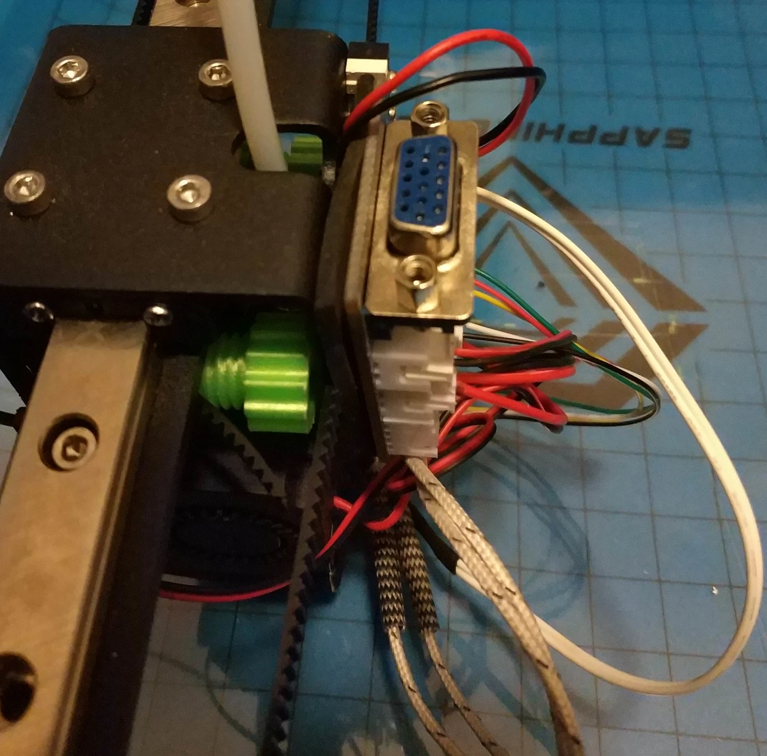
Step 3. Connecting
Once everything is connected on the hotend side, we need to connect the wire on the motherboard side. I've decided to dedicate 3 wires for the ground in the cable, but on the motherboard, those 3 wires must be exploded to 6 wires, so I've soldered a 6 wires harness to the 3 wires from the cable and protected all of them in a heat shrink tube. Since the wire in the motherboard area are not moving, you can solder them if it's easier for you. I've decided to crimp the wire and plug them in JST connectors so I can swap the cable if it happens to be damaged.
The cable, once connected looks like this:
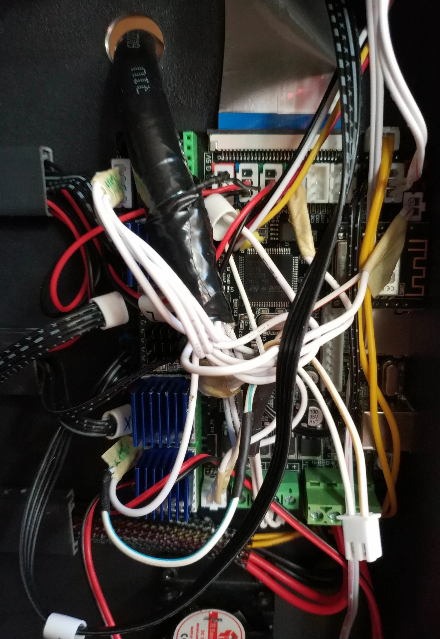
Beware however that the thermistor wire should not go over the WIFI module (like in the picture above), but must avoid it. I had inconsistent reading of the hotend temperature until I moved it out of the WIFI waves. I could have shielded it also.
Sponsored links
In order to pay for infrastructure cost for this blog, I'm listing some affiliated links about the hardware listed above.


