Assembly tips for Sapphire Plus 3D Printer - Step 4
Step 6: Installing the belts
I made a mistake when installing the belt, since I haven't measured the provided belt beforehand (I expected to have a lot of margin so I cut the belt for the X motor with 10cm margin and was then short of 3 or 4 cm on the Y motor's belt). Hopefully the belt is not expensive and you can get a new one 2 days later, make sure to order a GT2 6mm belt if it happens to you. They only provide the right length of the belt, so make sure before cutting it.
I'm not going to show you how to install the belt (it's quite easy, follow the manual on the SD card so you can zoom in).
Step 7: Tensioning the belts
This is the most important step of a CoreXY printer, and yet, it's not described in anyway on the manual nor on the tutorial video. So, I'll try to better explain this point, since I had multiple printing issues because my belts were not tensioned correctly. You'll need to move the extrusion head in the middle of the printer (above the hotbed's SapphirePlus logo). This is to make sure that the length of the belts is the same on the back of the printer where we'll measure them. If you already have a 3D printer, print and construct this belt tension gauge else, you'll have to tighten them manually for your first print and later re-tension them.
If you have to tighten them manually, I'll say that the belts are tensioned correctly when they both sound like a very bass E when plucked. They must sound the same when the head is in the center of the hotbed. They will not sound the same if the head is elsewhere.
With the belt tension gauge, you'll have to measure the same tension when they are correctly tensionned (again, if the head is in the middle of the bed).
If you are, like me, finding that holding the belt with a plastic strap is not very clean, you can print 2 or 4 of these belt tensioners. I had to scale the nut 105% on XY axis before slicing and the screw 102% on XY axis so they fit better once the belt is inserted.
Step 8: Mounting the Extruder
Unlike what the manual says (in fact it's saying something on the printed page and something else on the PDF file), you should mount the extruder on the front right column, when looking that the machine with the screen in front of you:
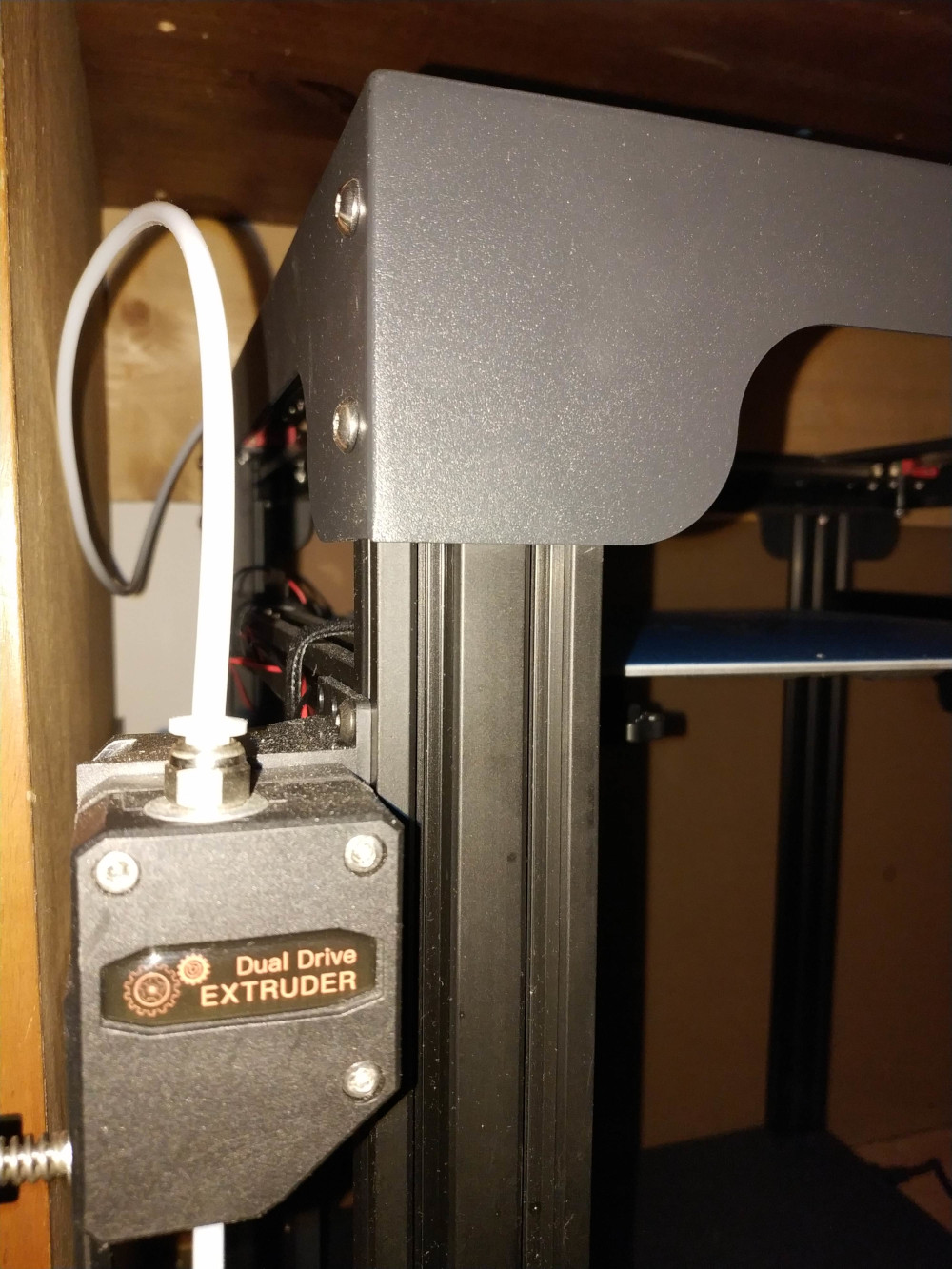
If you never have built an extruder, the order for the external screw is: Screw - Spring - Washer - Extruder.
Step 9: Plug all cables
You'll need to follow the pinout on the previous page to plug each cable where it's expected. I've slided all cable inside the bottom cable trays so that they don't balance unattached. The colors are important, X is red, Y is blue, Z is green and Extruder is black. So if unsure about a cable, match the color, it'd work.
The filament sensor was wrongly wired on my system, so it couldn't work. You can easily check with your multimeter if the contact happens when the filament is present and if it changes when it's not. On my system, it didn't (no contact was either made between any of the pins). I switched the wires in the JST connector so that the contact are made when the filament is not present. Since there is only 2 wires on the 3 pins connector, you only need to swap wires on the filament sensor's side (don't touch on the side that's plugged on the main boad, or it'll not work).
The contact is made if you read 0 ohm when the filament isn't present and infinite resistance when it is.
The correct wiring looks like this:
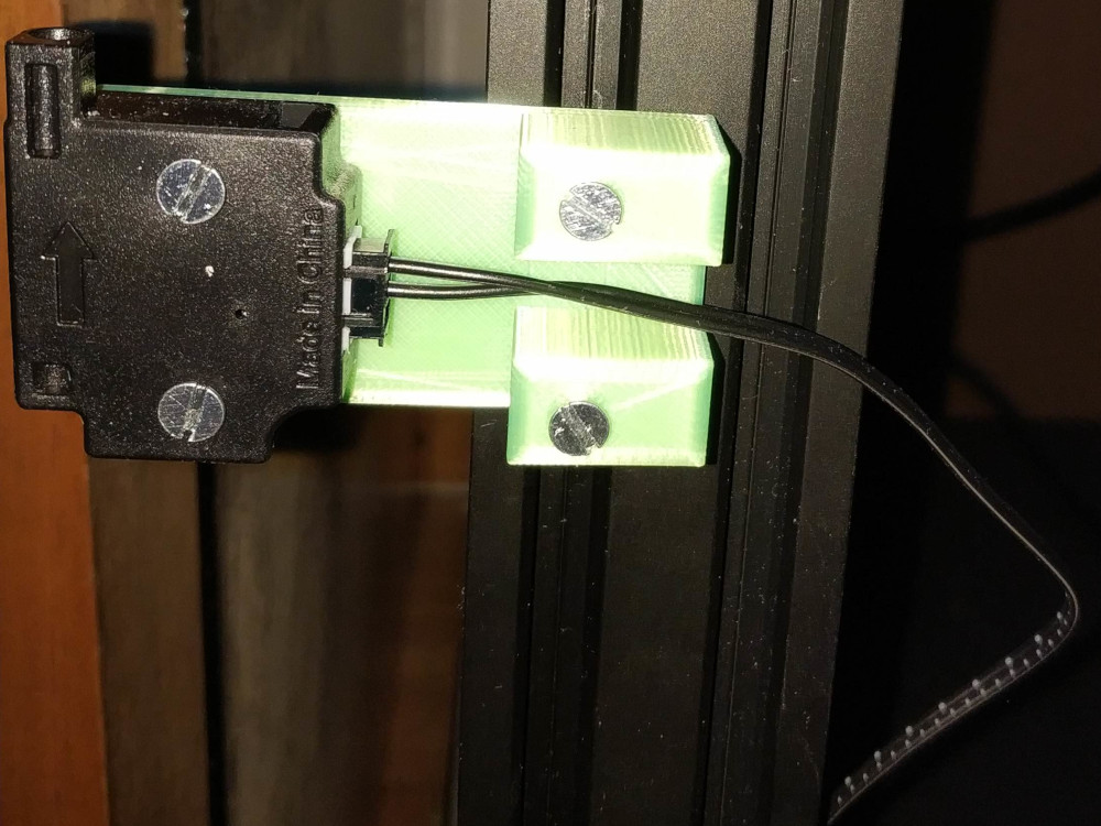
For the 3D model of the support to screw the detector upon, click here.
Step 10: Powering up
Ok, so you've finished building your printer.
Switch on the printer, and try to home each axis. Then move them all the way and make sure it doesn't make any strange noise, skip steps or something like this.